
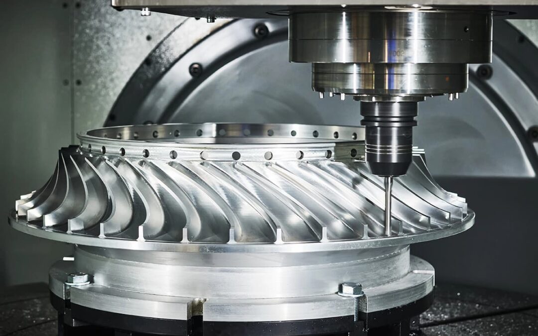
If you’re writing or reviewing a process plan for a hybrid-manufactured part — SLM-printed blank, CNC-finished to drawing — the machining allowance is the number that determines whether the finished part cleans up or gets scrapped. For flight-critical hardware, it should be the first thing on the planning sheet, not the last.
Quick Summary: SLM as-printed tolerance degrades with part size: ±0.1–0.2mm under 100mm, opening up to ±0.4–0.5mm above 300mm. Stock allowance for CNC finishing runs 0.3–0.5mm per side for standard features, 0.5–0.75mm for bearing seats and sealing surfaces, 3–6mm for wire-arc deposited features. You need two CAD models, stress relief before machining, and a blank inspection before committing CNC time.
What Determines As-Printed Accuracy?
SLM builds parts by melting powder with a laser, layer by layer. Every solidification cycle introduces thermal distortion, and that distortion accumulates across the build height. The result: dimensional accuracy gets worse as parts get bigger. Not surprising, but the rate is predictable enough to plan around.
| Part Size | Typical As-Printed Tolerance |
|---|---|
| Under 100mm | ±0.1–0.2mm |
| 100–200mm | ±0.2–0.3mm |
| 200–300mm | ±0.3–0.4mm |
| 300–400mm | ±0.4–0.5mm |
Surface roughness runs Ra 6–20μm on vertical and angled walls. Downskin surfaces — overhangs, the underside of features — run Ra 20–30μm or worse. Support removal marks add localized roughness on top of that. These numbers establish the tolerance budget that machining has to close.
How Do You Calculate the Allowance?
The machining allowance is the extra material on the print body so the CNC finish pass cuts entirely into clean, fully dense material — clearing roughness, support scars, and minor distortion. Too thin and the cutter rides over valleys. Too thick and you waste print time and machine time.
Stock allowance per side:
External surfaces: 0.3–0.5mm. Enough to clear surface roughness and minor distortion on small-to-medium parts.
Bores and internal cylinders: 0.3–0.5mm. Print the hole undersize so the boring or reaming pass opens it to final diameter.
External cylinders: 0.3–0.5mm oversize. Turning or grinding brings the OD down.
Large parts (over 200mm): 0.5–1.0mm. More cumulative distortion needs more stock.
Bearing seats, sealing faces: 0.5–0.75mm minimum. A partially machined bearing seat is scrap. There is no salvage operation, and on a $2,000 printed blank, that’s an expensive lesson.
WAAM (wire arc): 3–6mm per side. The weld bead profile is far rougher and more variable than laser-fused powder.
The math:
External: Print dimension = Finished + (2 × stock per side) Bore: Print dimension = Finished − (2 × stock per side) One-sided face: Print dimension = Finished + (1 × stock)
Why Two CAD Models?
The process plan should reference two distinct solid models:
Model A — Finished Part. The engineering drawing geometry with nominal dimensions and GD&T per ASME Y14.5. The CNC program machines to this. First-article inspection measures against this.
Model B — Print Body. The oversized (or undersized, for bores) geometry sent to the SLM machine. Machine-final surfaces are offset by the stock allowance. Print-final features stay at nominal.
Link them parametrically so a design change to Model A updates Model B. The most common planning error we see is updating one and forgetting the other — you end up with either insufficient stock or an overbuilt blank that wastes machine time on both ends of the process.
What Has to Happen Before Machining?
Stress relief. This is non-negotiable for structural parts. Residual stress from the SLM process causes the part to distort when you remove material during machining. The distortion shows up after the CNC pass, not during it. The part checks good on the machine, then shifts out of spec. Same phenomenon that drives heat treatment requirements on forged or cast blanks — same fix.
Typical sequence: print (on build plate) → stress relieve (still on build plate) → remove from plate → heat treat per material spec → inspect blank → machine.
Blank inspection. Before loading the blank, scan it against Model B. A CMM or structured-light scan confirms that every machine-final surface has enough stock, and that your fixturing datums are where you expect them. This step catches problems when they’re still recoverable — before a $500/hour machine is loaded with a blank that was never going to clean up.
Threads, Shrinkage, and Build Orientation
Threads: Don’t print them. SLM thread-like features lack the form geometry and surface finish to engage a fastener to the 6H tolerance class. Drill to tap-drill diameter, chamfer, tap. Same process as any conventionally machined part.
Shrinkage compensation: The SLM machine applies a scale factor to compensate for solidification shrinkage. Build-prep software handles this. Confirm with the fabricator whether your stock allowance is specified before or after compensation. Double-applied compensation makes the blank oversize. Missed compensation makes it undersize.
Build orientation: Orient critical machined surfaces parallel or perpendicular to the build plate — best accuracy, smoothest surfaces. Don’t put supports on machine-final surfaces; if the support scar is deeper than your stock allowance, that surface won’t clean up. And plan the build with CNC fixturing in mind — you need a clamping surface that can be gripped without distorting the part.
Does the Alloy Change the Recipe?
Process is identical. Numbers shift. Titanium (Ti-6Al-4V) and Inconel distort more — budget 0.5–0.75mm per side. Stainless steels are well-behaved at 0.3–0.5mm. Maraging steels have good dimensional stability but different heat treatment requirements.
Validate with dimensional test coupons on your machine, your alloy, your parameter set. Published ranges are planning inputs, not guarantees. We apply the same principle to every aerospace blank that comes through our shop — whether it started as bar stock, a forging, or a powder bed. The documentation trail (material cert, process parameters, heat treatment records, dimensional inspection per ASME Y14.5) doesn’t change because the blank came from a printer.
Written by James Wright, CEO of Accurate Machine & Tool.
Sources
[1] Forge Labs DMLS Design Guide, forgelabs.com
[2] 3DPrintMap, “3D Printing Tolerances and Dimensional Accuracy Explained,” 2026
[3] MX3D, “Managing Machining Allowances for Near Net Shape Metal Prints,” 2026
[4] ISO/ASTM 52902
[5] ASME Y14.5-2009, B46.1